🎮 Bossy: Multiplexer Test 2
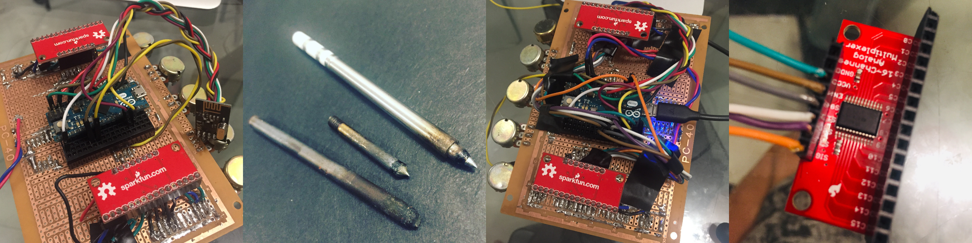
I hooked everything up to the multiplexers and it was really difficult, not only because of the soldering iron tip at hand, but also because I don’t have much available wires left. I cut six differently colored dupont cables and soldered the stranded wires which I hooked up to the multiplexer. It’s a bit delicate as of the moment. Might fix this to be more sturdy, maybe in the future.
PROTIP: How NOT to solder 101
- step 1: Insist on using the worst soldering iron tip ever because it’s the only one available at the moment
- step 2: Embarrass yourself by posting the result online
IMPORTANT! I found out that one of joysticks indeed has a faulty y-axis.
IMPORTANT! I noticed that the select buttons of the joysticks when pressed correlates with the y-axis readings of the joysticks. I looked up the schematics again and realized that the select button didn’t have a pull-down or pull-up resistor which I assumed (why did I assume this? Because I was being stupid, that’s why, elementary mistake). Because of how delicate the whole setup is I’m choosing not to solder such resistor for now. I’ll try to compensate with code for the meantime. Maybe in the future I’ll correct this mistake.
Anyway, I test the connectivity of the wires by checking each and everyone of the inputs. And observing if it behaves the way I expected.
Here’s the code.
int s0 = 5;
int s1 = 6;
int s2 = 7;
int s3 = 8;

int mux1_enable_pin = 11;
int mux2_enable_pin = 12;

int value = 0;
int value1 = 0;
int value2 = 0;

int sig_pin = A1;

void setup(){
  pinMode(s0, OUTPUT);
  pinMode(s1, OUTPUT);
  pinMode(s2, OUTPUT);
  pinMode(s3, OUTPUT);

  pinMode(mux1_enable_pin, OUTPUT);
  pinMode(mux2_enable_pin, OUTPUT);

  digitalWrite(s0, LOW);
  digitalWrite(s1, LOW);
  digitalWrite(s2, LOW);
  digitalWrite(s3, LOW);

  // Pulling down enable pin to ground enables the multiplexer
  digitalWrite(mux1_enable_pin, HIGH);
  digitalWrite(mux2_enable_pin, HIGH);

  Serial.begin(9600);
}

void loop(){

  // mux 1 my left
  Serial.print("mux1: ");
  enable_mux1();

  read_and_print(0); // 0 - upper button - pushed is 0
  read_and_print(3); // 3 - lower button - pushed is 0

  // lower left joystick labeled #2
  read_and_print(4); // 4 - select button - pushed is 0
  read_and_print(5); // 5 - y-axis up=0 , neutral=511, right=1022
  read_and_print(6); // 6 - x-axis left=1022, neutral=508, right=0

  // upper left joystick labeled #3
  read_and_print(7); // 7 - x-axis, left=1017, neutral=496, right=2
  read_and_print(8); // 8 - y-axis, up=0, neutral=508, down=1021
  read_and_print(9); // 9 - select button - pushed is 0

  read_and_print(10); // 10 - lower spdt switch - knob to the left is zero
  read_and_print(11); // 11 - upper spdt switch - knob to the left is zero

  read_and_print(12); // 12 - 2nd to the left potentiometer
  read_and_print(13); // 13 - center potentiometer
  read_and_print(14); // 14 - most left potentiometer
  Serial.println();

  // mux 2 my right
  Serial.print("mux2: ");
  enable_mux2();

  read_and_print(13); // upper button - 1023 is pressed
  read_and_print(12); // lower button - 1023 is pressed

  // lower right joystick - labeled #1
  read_and_print(11); //yaxis- down=0, neutral=497,, up=1022
  read_and_print(10); // select button - pushed is 0
  read_and_print(9); // x-axis- left=0, 509=neutral, right=1022

  // upper right joystick labeled #4
  read_and_print(8); // select button - pushed is 0
  read_and_print(7); // The joystick y axis is not working, verified. Connection is good, the joystick is malfunctioning.
  read_and_print(6); // xaxis left=zero, 518=neutral, 1022=right

  read_and_print(5); // lower spdt switch left=1023, neutral=510, right=0
  read_and_print(4); // upper spdt switch left=1023, neutral=510, right=0
  read_and_print(3); // second to the right potentiometer
  read_and_print(2); // most right potentiometer

  Serial.println();
  Serial.println("-");
  delay(1000);
}

void enable_mux1() {
  digitalWrite(mux1_enable_pin, LOW);
  digitalWrite(mux2_enable_pin, HIGH);
}

void enable_mux2() {
  digitalWrite(mux1_enable_pin, HIGH);
  digitalWrite(mux2_enable_pin, LOW);
}

int readMux(int channel){

  int controlPin[] = {s0, s1, s2, s3};

  int muxChannel[16][4]= {
    {0,0,0,0}, //channel 0
    {1,0,0,0}, //channel 1
    {0,1,0,0}, //channel 2
    {1,1,0,0}, //channel 3
    {0,0,1,0}, //channel 4
    {1,0,1,0}, //channel 5
    {0,1,1,0}, //channel 6
    {1,1,1,0}, //channel 7
    {0,0,0,1}, //channel 8
    {1,0,0,1}, //channel 9
    {0,1,0,1}, //channel 10
    {1,1,0,1}, //channel 11
    {0,0,1,1}, //channel 12
    {1,0,1,1}, //channel 13
    {0,1,1,1}, //channel 14
    {1,1,1,1}  //channel 15
  };

  //loop through the 4 control pins
  for(int i = 0; i < 4; i ++){
    digitalWrite(controlPin[i], muxChannel[channel][i]);
  }

  //read the value at the SIG pin
  int val = analogRead(sig_pin);
  return val;
}

void read_and_print(int ch) {
  value = readMux(ch);
  Serial.print(value);
  Serial.print(" | ");
}