🎮 Bossy: Soldered Components
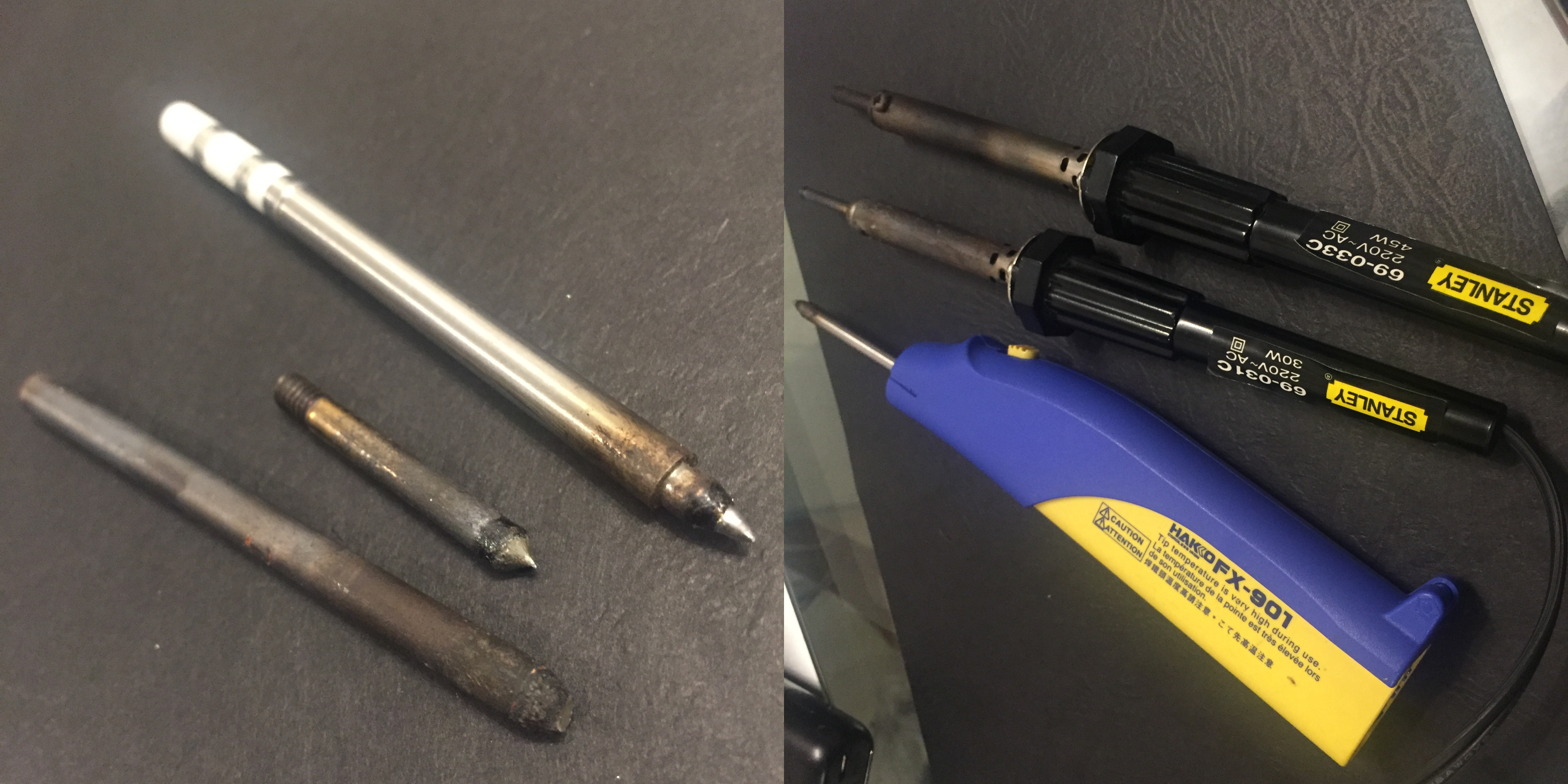
Note to self: Invest in a good soldering iron. Currently I only have a cordless AA-powered Hakko soldering iron, which is great, until after 15 minutes, it isn’t, and you have to change the battery, it gets expensive fast.
I can’t buy right now having the extreme quarantine due to covid19, so I borrowed from a neighbor from the other floor. It heats up nicely but tip was really bad. The picture on the left are the soldering tips, the most right soldering tip is mine, the other two is from what I borrowed. As you can see, mine looks pretty good, the left most is unusable. You can’t even interchange the tips as you may have already noticed, Hakko tip is too fat to fit the others, and one of the Stanley ones is a screw-in type.
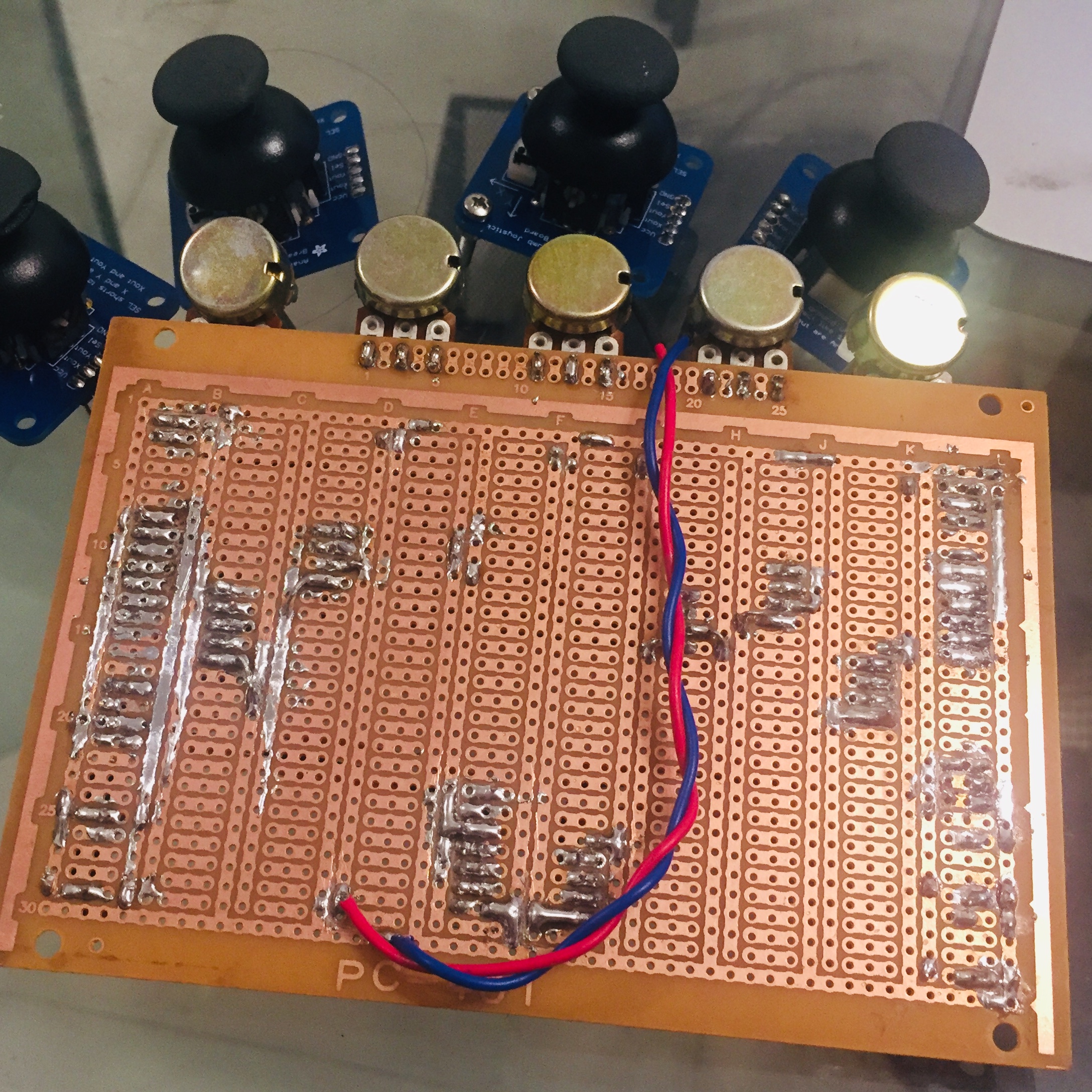
Despite this, I was able to solder everything in stripboard. Not gonna lie, it looks really ugly and dirty. With a better iron, I could do better. I know I’m sounding like I’m making excuses, but anyway. It looks dirty but hey, nothing is shorting and everything works.
 |
 |
|---|---|
 |
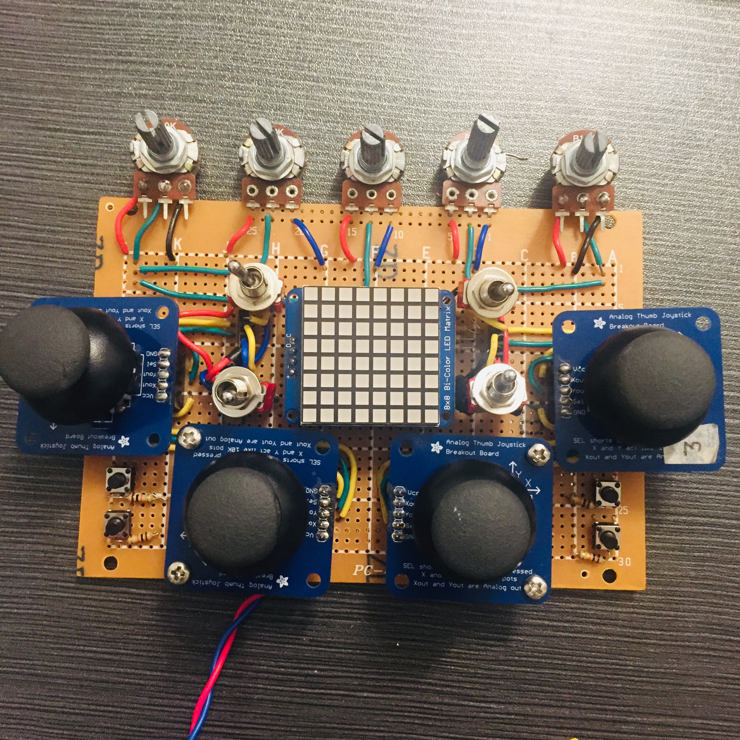 |
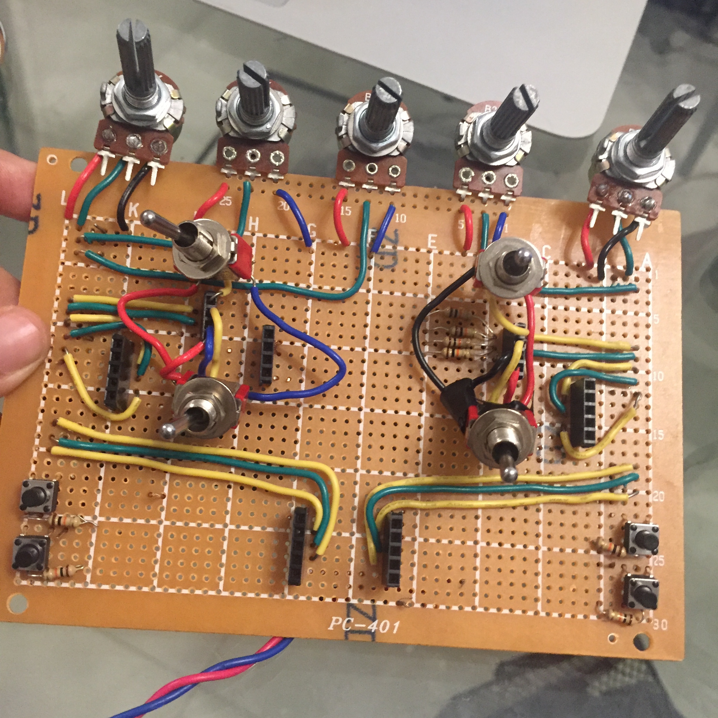
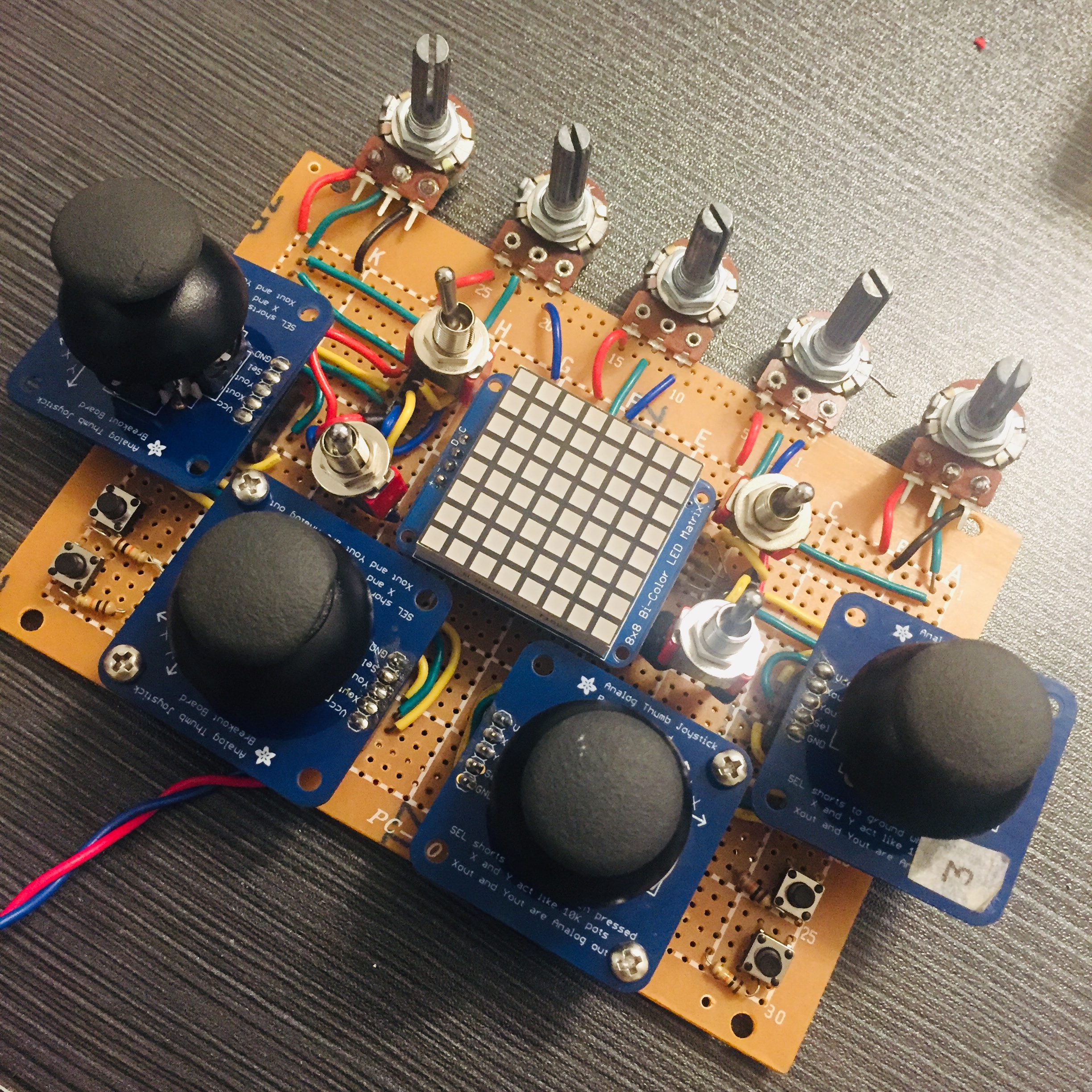
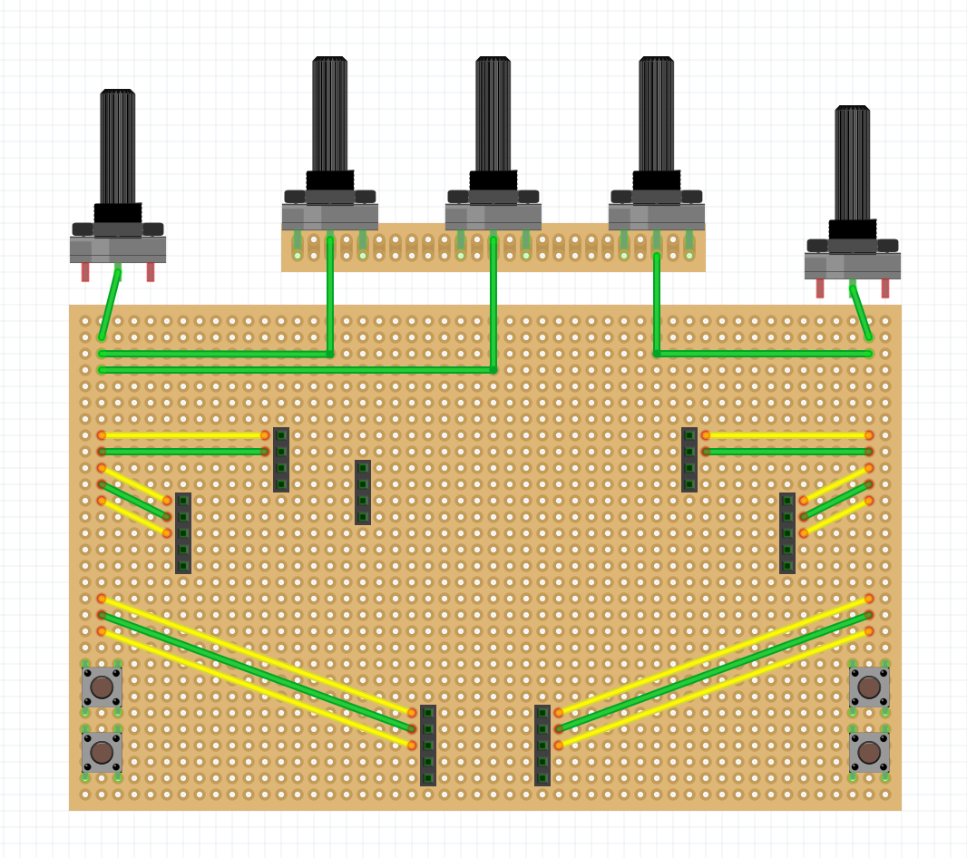
Here’s how it’s wired from the top
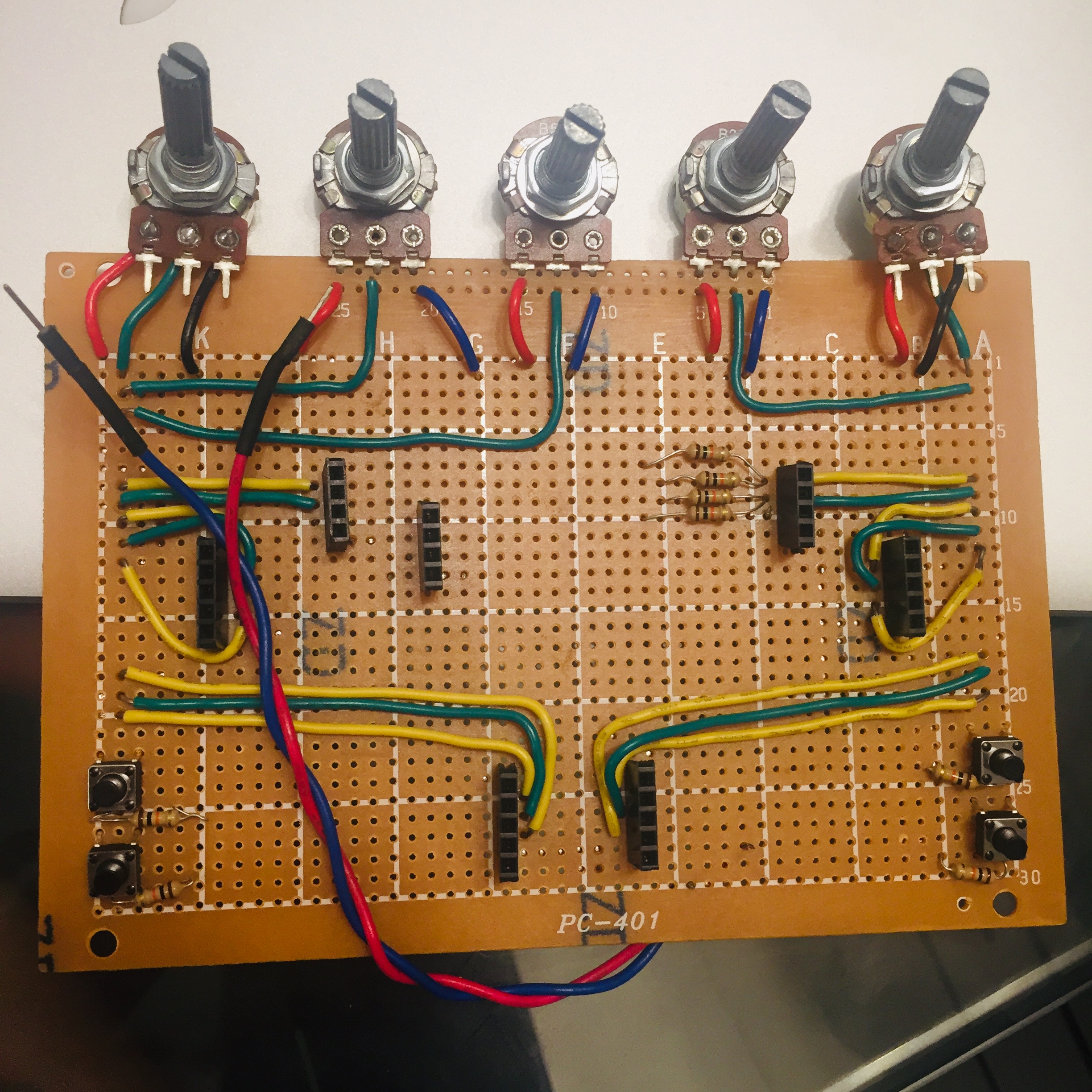
If I could turn back time a few ways ago, I would have soldered the joysticks a little different so that the wiring would be more elegant.
-
- Move the upper left joystick one hole to the right
-
- Move the upper right joystick one hole to the left
-
- Move the lower left joystick one hole to the right
-
- Move the lower right joystick one hole to the left
It would have been much cleaner!
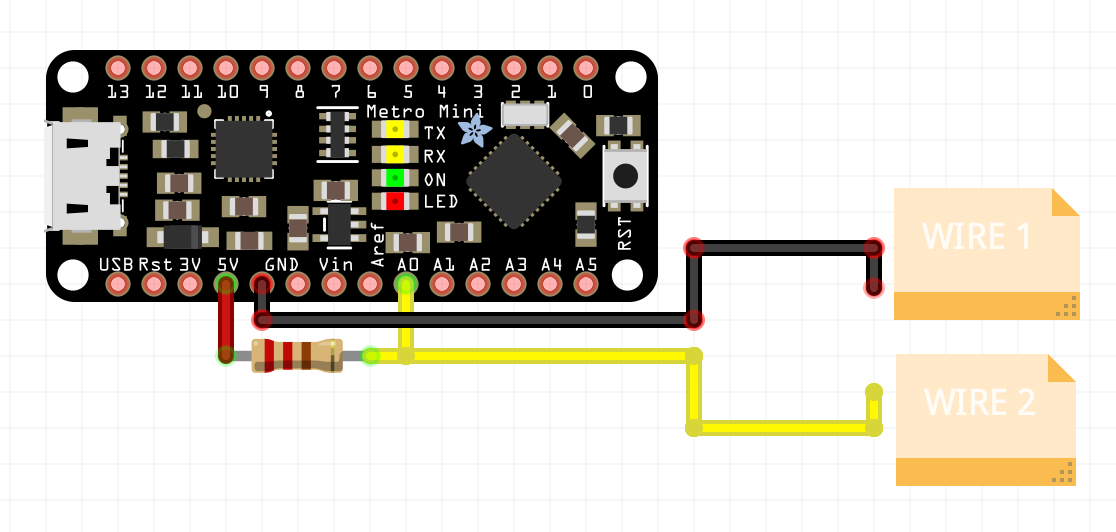
Makeshift wiring tester
- Moving on, I found out that it would be better to use an analog pin
instead of a digital pin to test the continuity. This is because
if you put a 10k ohm resistor inbetween the two wires, a digital pin will
still read a
LOW. I usedA0pin pulled up. While I’m at it I also used this setup to test the joysticks, buttons, potentiometer, spdt switches etc.
IMPORTANT: All the joystick pins were perfectly fine, except for Yout of one of the joysticks, it wasn’t as consistent but can be compensated with code
 Note when testing if the
 VCC busline and the GND busline of the stripboard are shorted,
A0 will not read a perfect 1023 because there are resistors between VCC
GND, so it will read around 100 - 200
// Continuity Tester
// pull-up resistor (10k ohms between A0 and 5V)

void setup() {
  Serial.begin(9600);
  pinMode(13, OUTPUT);
}

void loop() {
  int x = analogRead(A0);
  Serial.println(x);

  // if x == 0 then the wires are shorted
  if (x < 1) {
    digitalWrite(13, HIGH);
  } else {
    digitalWrite(13, LOW);
  }
}