🎮 Bossy: Wireless Test
- Make one Arduino Micro send a message
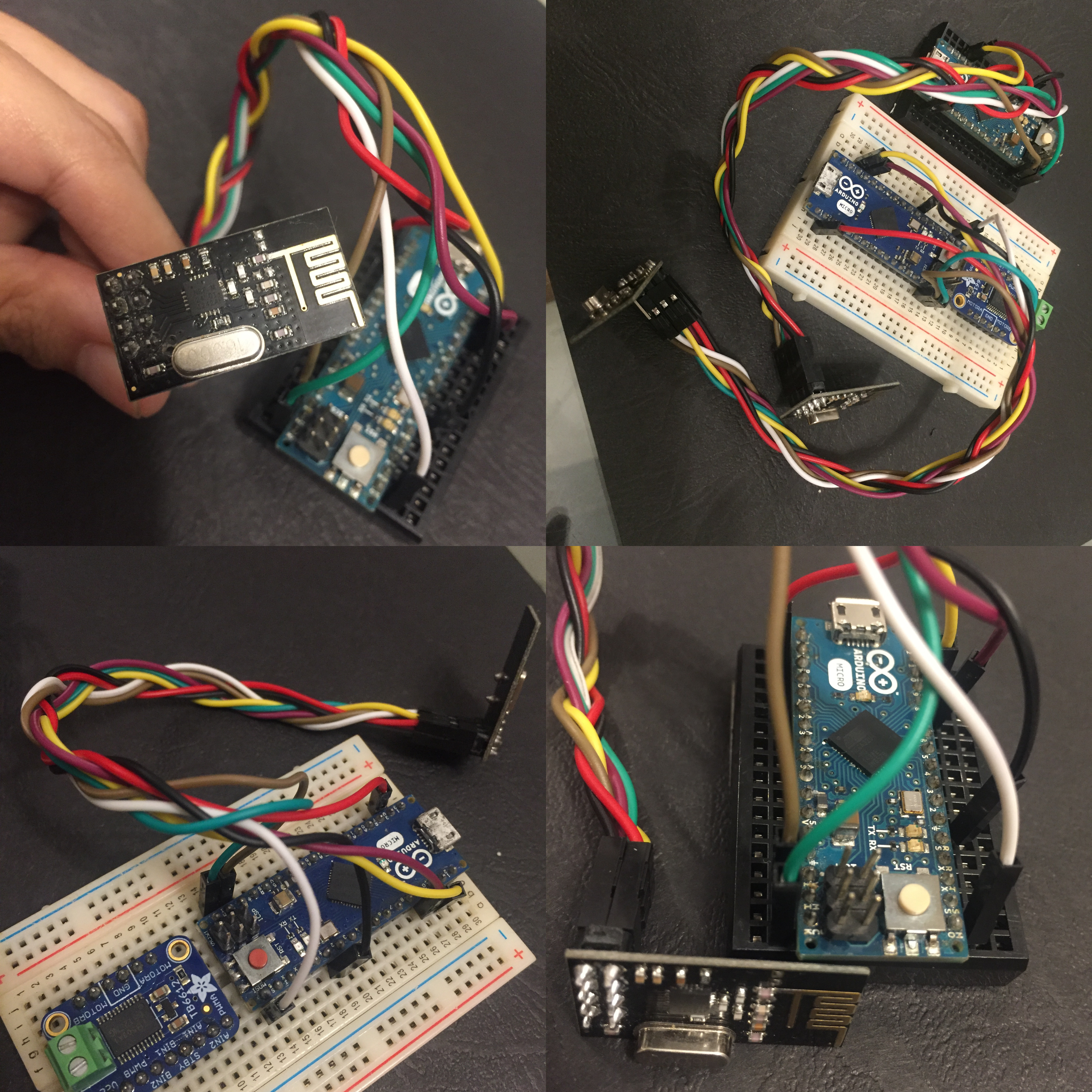
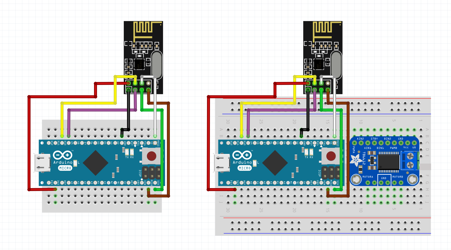
"Hello world! Watchout!"and another Arduino Micro receive it usingnrf24l01modules - Took me two whole days to get this thing up and running
- I used this library: nRF24/nRF24, documentation by tmrh20
- Ignore the TB6612 breakout board
| color | pin | pin | color |
|---|---|---|---|
| brown | miso | irq | nc |
| green | sck | mosi | white |
| violet | ce | csn | yellow |
| black | gnd | vcc | red |
Transmitter Code
#include <SPI.h>
#include <nRF24L01.h>
#include <RF24.h>
#include <printf.h>

#define CE_PIN 9
#define CSN_PIN 10
RF24 radio(CE_PIN, CSN_PIN);

const byte ADDRESS[6] = "00001";
const char TEXT[] = "Hello world! Watchout!";

void setup(){
 while (!Serial);
 Serial.begin(9600);
 printf_begin();
 radio.begin();
 //radio.setAutoAck(false);

 radio.setDataRate(RF24_2MBPS);
 //RF24_1MBPS

 radio.setPALevel(RF24_PA_MIN);
 //RF24_PA_LOW

 radio.setRetries(3, 5);
 //delay, count

 radio.openWritingPipe(ADDRESS);
 radio.stopListening();
 radio.printDetails();
}

void loop(){
 radio.write(&TEXT, sizeof(TEXT));
 delay(1000);
}
Receiver Code
#include <SPI.h>
#include <nRF24L01.h>
#include <RF24.h>
#include <printf.h>

#define CE_PIN 9
#define CSN_PIN 10

RF24 radio(CE_PIN, CSN_PIN);
const byte ADDRESS[6] = "00001";

void setup() {
  while (!Serial);
  Serial.begin(9600);
  printf_begin();
  radio.begin();
  //radio.setAutoAck(false);

  radio.setDataRate(RF24_2MBPS);
  //RF24_1MBPS

  radio.setPALevel(RF24_PA_MIN);
  //RF24_PA_LOW

  radio.setRetries(3,5);
  //delay, count

  radio.openReadingPipe(0, ADDRESS);
  radio.startListening();

  radio.printDetails();
}

void loop() {
  if (radio.available()) {
    char text[32] = "";
    radio.read(&text, sizeof(text));
    Serial.println(text);
  }
}
Troubleshooting Tips
-
Doublecheck all your connection wires, vcc should be connect to 3v, connecting it to 5V will fry your board.
-
Be sure to include
#include <printf.h>andprintf_begin();to be able to printradio.printDetails()on Serial monitor -
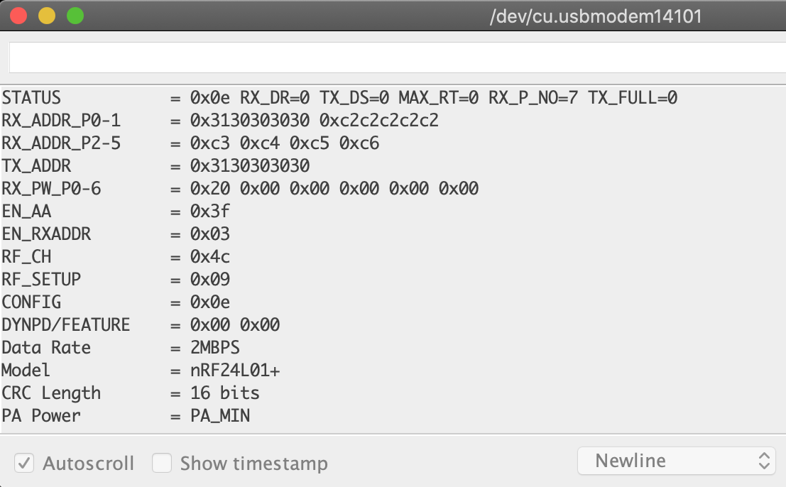
If your nRF24l01 is working properly, you’ll be able to print details with
radio.printDetails()of your module in the serial monitor.- Pay attention to the
Model,Data RateandPA Powerrows. - If you set the
Data RatetoRF24_2MBPSis should reflect that. - If you set
PA PowertoRF24_PA_LOWit should reflect that.
- Pay attention to the
Try these if it’s still not working (I didn’t need them)
- Due to some manufacturers’ poor soldering quality and improper storage, some modules might end up with a grey “crust” over the pins and the underside of the crystal oscillator This crust can affect the conductivity and/or create electrical noise. Remove the crust with a small flat screwdriver or tooth pick and wipe the remaining dust using a dry cloth -Julio Vazquez Vexelius . Instructables
- Solder a 10 uF electrolytic capacitor ground and power. Take note of the polarity. The capacitor is to make sure there is enough power being supplied when it needs it. Without the capacitor it causes unreliable communication.
- Place a capacitor of 100uF between 3.3V and GND of Arduino when using NRF24L01+ because it draws more current than NRF24L01 -The Engineering Projects
- Add
radio.setAutoAck(false);afterradio.begin()- Vitaliy D - Watch this video by Ralph S Bacon